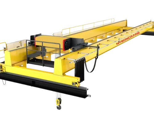
Proper engineering of the runway beam and building column foundations is the foundational safety requirement for any industrial bridge crane installation. An accurately calculated overhead crane runway design prevents structural deflection, excessive crane wheel flange wear, and catastrophic fatigue failure across your facility’s steel framework.
Engineering Rule of Thumb for Runway Planners
Runway girder design must account for Vertical Wheel Loads (Deadweight + Rated Capacity + Dynamic Impact Factor), Lateral Side Thrust (minimum 10% of total lifted load + trolley weight), and Longitudinal Tractive Force (minimum 10% of total crane weight). Vertical deflection must strictly comply with CMAA Specification 70/74 and ISO standards (maximum L/600 to L/1000).
1. Understanding Key Runway Forces & Wheel Load Calculations
When an overhead crane system operates, dynamic stresses are transmitted through the crane end carriages and beam components into the runway girders and building columns. Structural engineers must evaluate three primary load vectors:
A. Maximum Vertical Wheel Load ($P_{max}$)
The maximum vertical load occurs when the hoist and trolley are carrying the 100% rated proof load positioned at the closest possible approach to one runway rail (minimum end approach distance):
Note: The dynamic impact factor typically ranges between 1.15 and 1.25 for standard electric hoists and up to 1.30 for high-speed top-running cabs.
B. Lateral Side Thrust (Skewing & Centrifugal Forces)
As the trolley starts, stops, or accelerates across the bridge, horizontal lateral forces act perpendicular to the runway rail. Standards require sizing runway beam top flanges to resist a minimum of 10% of the combined weight of the trolley and rated lifted load.
C. Longitudinal Braking Forces
When the long-travel bridge motors engage their emergency or parking brakes, longitudinal forces act parallel to the crane rail. Runway column tiebacks, bracing, and anchor bolts must absorb this thrust without transferring torsion into building sidewall panels.
2. Runway Girder Deflection & Alignment Tolerances
Excessive runway beam deflection causes the crane bridge to skew, inducing severe rail binding, premature DRS wheel block wear, and motor overloads.
| Crane Configuration | Max Vertical Deflection Ratio | Max Horizontal Deflection Ratio | Rail Gauge Tolerance (ΔS) |
|---|---|---|---|
| Single Girder Crane (A3–A5) | L / 600 (Span / 600) | L / 400 | ± 3 mm to ± 5 mm |
| Double Girder Crane (A5–A7) | L / 800 (Span / 800) | L / 500 | ± 2 mm to ± 3 mm |
| Heavy Mill / Ladle Crane (A8) | L / 1000 (Span / 1000) | L / 600 | ± 2 mm maximum |
Planning your facility budget? Refer to our comprehensive overhead crane cost guide for structural steel and equipment pricing benchmarks.
3. Building Column & Foundation Footing Design Guidelines
1. Standalone Runway Columns vs. Building Bracket Supports
For existing facilities without pre-engineered crane brackets on building columns, installing freestanding structural runway columns is the safest approach. This completely decouples crane dynamic vibrations from the facility roof trusses and exterior curtain walls.
2. Soil Bearing Capacity & Concrete Footing Depth
Heavy double girder cranes require reinforced concrete pad footings or deep drilled pier foundations. Soil core test reports should confirm an allowable soil bearing capacity of at least 150 kPa to 250 kPa. Embedment depth of high-strength anchor bolts (Grade 8.8 or ASTM A325) must resist both vertical compression and overturning bending moments.
3. Rail Clamping & Continuous Welded Rails
For smooth crane travel, adjustable rail clips with vulcanized synthetic rubber nose pads (such as Gantrex or standard weldable clips) should be utilized. These clips absorb acoustic vibration, compensate for thermal expansion, and prevent rail bolts from shearing under cyclic fatigue.
Not sure whether single or double girder configuration fits your building headroom? Read our single girder vs double girder comparison guide.
Need Runway Wheel Load Calculations for Your Structural Engineer?
Nybon Machinery supplies complimentary crane bridge layout CAD drawings, exact static/dynamic wheel load data sheets, and runway beam sizing consultations.
4. Frequently Asked Questions (FAQ)
Q1: What happens if runway rails are out of parallel alignment?
Out-of-gauge runway rails cause severe wheel binding, loud squealing, high motor amp draw, and dangerous rail climb. In extreme cases, misaligned rails can fracture bridge wheel flanges or loosen structural tieback bolts.
Q2: What steel profiles are standard for overhead crane runway beams?
For light-to-medium single girder cranes (1–10 tons), standard wide-flange W-beams (H-beams) with cap channels welded to the top flange are most common. For spans over 12 meters or capacities exceeding 20 tons, custom welded plate girders or box girders are engineered to resist lateral buckling.
Q3: How often should runway beams and rail alignment be inspected?
Optical or laser runway alignment surveys should be conducted annually for high-duty production cranes, and at least once every two years for general maintenance workshop cranes.